Hydrodynamics !
- captdan
- Jun 24, 2020
- 2 min read
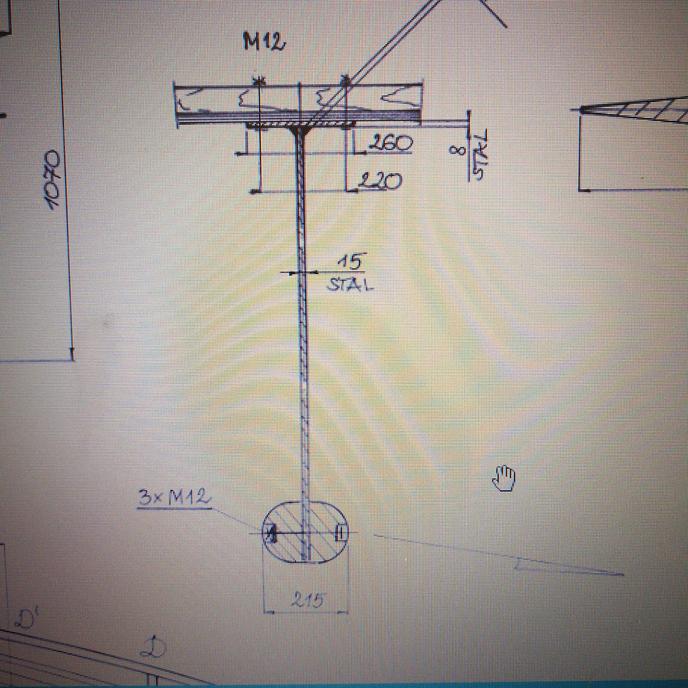
The keel on the Class Globe isn't going to provide a lot in the way of lift because of its design but sometimes simplicity is the best solution. The keel will be manufactured from a 15mm steel plate which is mounted to the hull by means of a 8mm steel plate as per the plans. Both of these could be either galvanized or epoxy painted after fabrication. At the bottom of the keel there will be lead bulb mounted to the keel plate by 3 bolts. The bulb will have to be poured in to a mold that is specified on the plans.
I have 3D modeled the bulb in Autodesk Fusion 360 which was a great help because the line projections gave me some needed dimensions. See pictures below. If you need the CAD file for your build, contact me and I will send you what I have. The weight of the lead is estimated to be 69 kg per half without the bolt holes opened up.
I constructed the mold from plywood and foam as pictured below. The only thing that I would do differently if I did it again would be to use all the same material for the foam. I used 25mm sheet material and some spray foam. The spray foam proved to be more dense and thus harder to shape compared to the other material.


Original drawings

Dimensions used for the wood / foam mold

3D mold for visual purposes
Note that there is a 20mm flat area where it meets the 15mm plate - Its shown on drawing Ark2 as a section view of the bulb. You can also see it in my layout on the plywood. Again, this is calculated at 69kg + -

6mm plywood used


Looks nasty at this stage ....

Starting to take shape by using a rasp file. I removed foam material until the plywood started to get exposed.

Almost done ..... The only thing I did from here was to fill in some of the holes with spray foam and file down to the profile. All of the measurements checked out - 760mm long and 160mm diameter at the fatty area !
Wahoo !!
This now will be turned upside down into a box and then we pour a medium that will setup and produce an internal mold. I will then pour molten lead ( sounds totally safe with now issues huh ? ) into the internal mold and let it setup. I have done this many times in the past to make babbit bearings for the Great Lakes freighter ships and some old grain elevators that still used that style of bearing. Not that hard but I learned a few tricks from a fellow Machinist that had been doing them since for ever !!! He used to say that he is so old that when he went to school, History wasnt even a subject that was studied yet ...... He was quite a character !
I still have some of his babbit scraping tools - they might come in handy, if I can find them ....


Comments